Ground Penetrating Radar (GPR) Proves to be Best Method for Pavement and Transverse Joint Evaluation

Columbus, Ohio (PRWEB) July 25, 2013 -- Resource International, Inc. (Rii)’s NDE and Technology division, under contract with the Ohio Department of Transportation, (ODOT), confirms Ground Penetrating Radar (GPR) is the best method for making recommendations for roadway repair.
Rii used GPR technology to evaluate the transverse joint conditions on HAN-75-3.22 consisting of 11.19 miles of Interstate 75 (I-75) in Hancock County, Ohio. The study included an evaluation of the conditions of the transverse contraction joints and location of sections of the pavement where voids may have developed under the reinforced concrete slabs. Both lanes in the northbound (NB) and southbound (SB) directions were surveyed. A visual inspection, and Pavement Condition Rating of the transverse joints was also performed.
Other Testing Methods
The conventional approach using the visual inspection does not reveal the existence of voids under slab and the structural integrity of concrete as it is overlaid by inches of asphaltic pavement. An enhancement of the conventional approach utilizing Falling Weight Deflectometer (FWD) has been effective in assessing the joint condition to determine the joint transfer load efficiency and to locate voids existing beneath the joints. However, this technique can be extremely time consuming and requires lane closure. In addition, the testing is only performed at some transverse joint locations.
Ground Penetrating Radar
Ground Penetrating radar (GPR) has been shown to be most effective at assessing a variety of highway applications, including bridge deck concrete deterioration, pavement thickness measurement, detection of voids under concrete pavement, and quality control measurement on new asphalt overlays. In the past few years, Rii has shown in a couple projects, performed on I-71 and I-74 for ODOT District 6 and District 8 that GPR is a tool that can reliably assess the condition of transverse contraction joints and locate voids under concrete slabs.
In the HAN-75-3.22 project, continuous data were collected using van-mounted horn antennas moving at a speed of 25 miles per hour. Figure 1 shows the survey vehicle used during data collection. The mobile GPR survey vehicle, equipped with flashing lights, complied with TA-35 MOT and required two shadow vehicles.
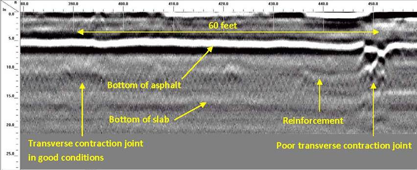
The software developed by the manufacturer of the GPR equipment Geophysical Survey Systems Incorporated (GSSI), was used to process the field data according to the procedure developed by GSSI and in compliance with ASTM D 6432-11 specifications. Figure 2 shows a typical GPR scan where we clearly see that the pavement is a JRCP with transverse joints spaced at regular intervals of 60 feet. The scan shows also the reinforcing steel that has been placed in the concrete slab, the bottom of the slab, and the bottom of asphalt, which in fact is the interface between the asphalt layer and the concrete slab. As shown in Figure 2, asphalt thickness is approximately 6 inches and the concrete slab is about 10 inches thick.
One could easily recognize on the GPR scan of Figure 2 the features of a deteriorated transverse contraction joint. The asphalt concrete interface is discontinuous, appearing as broken or settled concrete slab. Sometimes a large void appears under the joints. The void is identified by looking at the reflection polarity showing as a white band followed by a black band and another white band. The transverse contraction joint on the left of the figure shows no evidence of voids and that the asphalt concrete interface is continuous, confirming that this joint is in good condition.
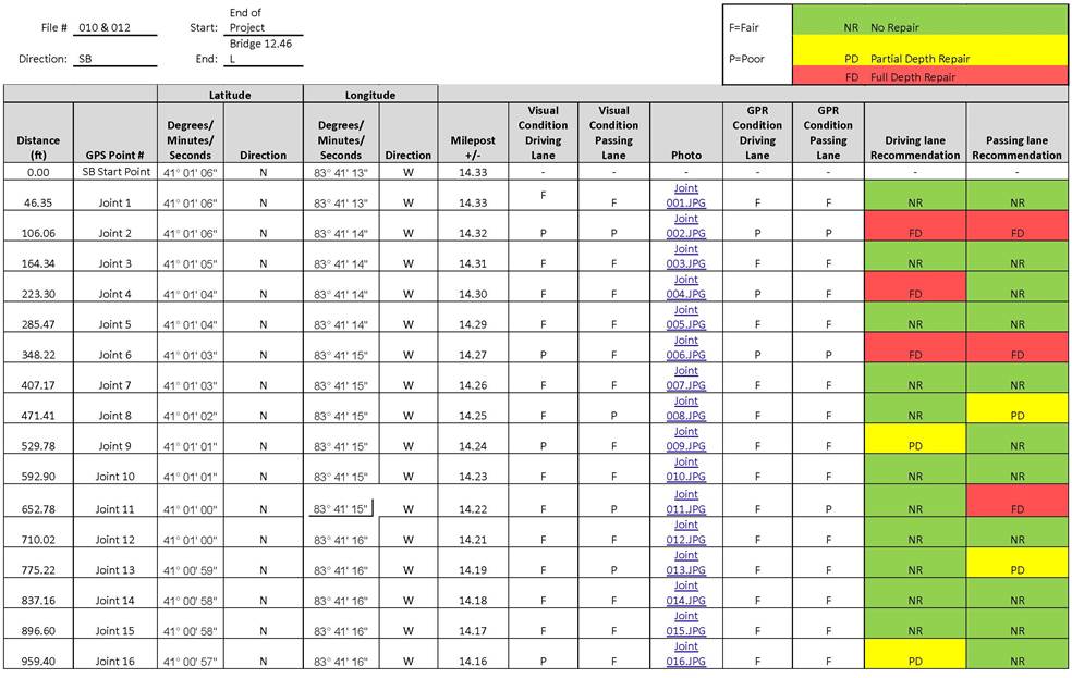
The conditions of each transverse joint for the 11.19 mile highway pavement were reported in Excel spreadsheets. Table 1 is a representation of the reported results. A click on the photograph number would show an image of the corresponding transverse contraction joint.
Rii also presented a field implementation plan to identify and locate each deteriorated joint in the field and perform required repair as recommended in the report.
Considering the high number of joints tested, Rii recommends to use a handheld GPS unit or Project Grid Mobile Asset Manager and the provided joint pictures to locate accurately each pavement joint in the field before repair. The quantities needed for the repair of the joints are estimated on the basis of the length of the joint to be repaired. Generally, it is assumed that this length is 6 feet or 2 yards. Since the width of the lane is 12 feet or 4 yards, each joint would require 8 square yards of repair. ODOT Item 251 – Partial Depth Pavement Repair – is recommended for joints needing partial depth repair and ODOT Item 252 – Full depth rigid pavement removal and flexible replacement – is recommended for joints needing full depth repair.
About Resource International, Inc.
Resource International, Inc. (Rii) is a broad-based, multi-disciplined professional engineering consulting firm specializing in construction management, information technology and planning and design of building and infrastructure projects valued in excess of $1 billion annually.
This family-run business has evolved over the years to assist public and private clients in finding optimum solutions to improve their environment and infrastructure. Our specialized equipment, technology and resources offer the best solutions.
Companywide, Rii has a deep pool of employees engaged in transportation planning, design, and construction services. Rii’s Corporate Office is located in Columbus, Ohio, with full-service branch offices in Cleveland and Cincinnati, Ohio; Pittsburgh, Pennsylvania; and Indianapolis, Indiana.
Cherif Amer-Yahia, PE, PhD, Resource International, Inc., http://www.ResourceInternational.com, 614-823-4949, [email protected]
Share this article